

Stimulus delivery computer
The facility is setup with a Windows-based desktop designed to be able to control your experiment, present stimuli, and gather responses. We strongly encourage you to use the machine rather than your own. Everything is wired and setup for this machine. If there are aspects about it that absolutely won’t work for your experiments, please let us know.
The computer uses an Intel i7 CPU (4.2-4.5 GHz, 7th Gen 7700k) with 16GB of RAM, and an NVIDIA GeForce GTX 1070 based graphics card (8GB RAM). It is fully configured to work with the BOLDScreen, fORP32 response box, eye tracker, and audio delivery system.
We have installed PsychoPy, E-Prime v2, and MATLAB /Octave + Psychtoolbox for running experiments. Contact us if there is another package you need. (E-Prime v2 and v3 users should be able to bring their license dongle).
Participant responses
The fiber-optic response box system from Cambridge Research has a range of devices for you to use. Typical experiments will use either the 8-button bimanual response box (two handheld boxes with 4 buttons each) or the 5-button one-handed cylinder. For both of these, the fORP 932 system 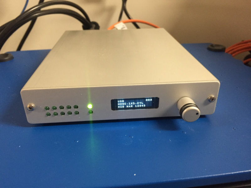 (user manual) translates the individual button presses into keyboard events (individual numbers corresponding to each button). We run it in “mode 003 – HID NAR 12345” which means it will report digits corresponding to each button and buttons being held down act as a keyboard being held down (i.e., they do not “auto-release”). “mode 001 – HID KEY 12345” is also a viable mode. The difference there is that pressing a key and holding it down acts like a simple press instead of a press and hold.
In either of these, responses come in as simple key events with numbers corresponding to actual buttons. As the “5” button is reserved for the scanner sync pulse (don’t ask), the 8-button system makes 1-4 and 6-9 responses while the 5-button cylinder makes 1 (thumb), 2 (yellow), 3 (green), 4 (red) and 6 (blue).
In addition, we have both a trackball (which acts as a standard 2-button mouse) and a joystick (which acts as a standard joystick but can be configured to act as a mouse) for your use.
Visual delivery
The facility uses a BOLDScreen32 LCD monitor (user manual) attached to the stimulus delivery computer. Unlike a typical projection setup, the LCD monitor lives inside the scan room, mounted at the back of the bore of the scanner and is viewed by just the single mirror on the headcoil. There are no other mirrors needed or rear-projection screens used, giving us an excellent image quality.
Turn it on and off using the small remote control affixed to the equipment room door. The top two buttons (1) control it and let you turn it on and off. You should hear the experimental computer chime when it gets turned on. Make sure the computer is awake or you won’t see the monitor turn on.
The system runs nominally at 1920×1080 pixels with a 120Hz framerate. It’s a 10-bit color depth (native) system that will accept 16-bit color depth input. Gray-to-gray response time is 5ms and contrast is 1400:1. Note, in addition to the native 1920×1080 resolution (which requires a dual-link DVI or DisplayPort input), a 1440×1080 100Hz rate is available if your video card cannot deliver the full resolution at the high refresh rate. The computer we provide runs at the full rate. Note, you cannot drive the display at other resolutions or rates. If you send fewer than 1080 lines, the manufacturer warns the panel may be damaged and if this happens, you will be responsible for the damage.
Audio delivery
For studies without audio, using the standard earplugs will suffice as the speakers built into the scanner are sufficiently loud to talk to your participants even when earplugs are in place. If you want to have them listen to sounds as part of your experiment, though, 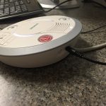 we have two means of delivering audio to your participants. The first uses Siemens built-in sound system. You can not only talk to, but also send sound through, the Siemens participant console by having either the computer or your own device (e.g., phone) plugged into the back of the participant communications device shown here.
Using this system, sound can go through the built-in speakers on the scanner or through the pneumatic headphones or in-ear headset (MagnaCoil) or both. The headphones likely won’t fit inside the head coil for you, but the in-ear headset works quite well. By having pneumatic tubes that go through foam earplugs, you can have decent sound with 30dB of attenuation. You can control the volume of the headset vs. in-room speakers in the participant comfort control on the scanner (Options, Configuration, Patient Comfort).
We also have a higher fidelity setup based 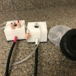 around a Cambridge Research MR Confon (now part of their BOLDfonic line) audio system (user manual) with high-fidelity earplugs. These have short air tubes (much like the Siemens in-ear style) that attach to special earplugs (pro-tip – trim the little red tube on the earplugs down like the one shown on the left). Put the white plastic boxes near the head coil, have the participant
 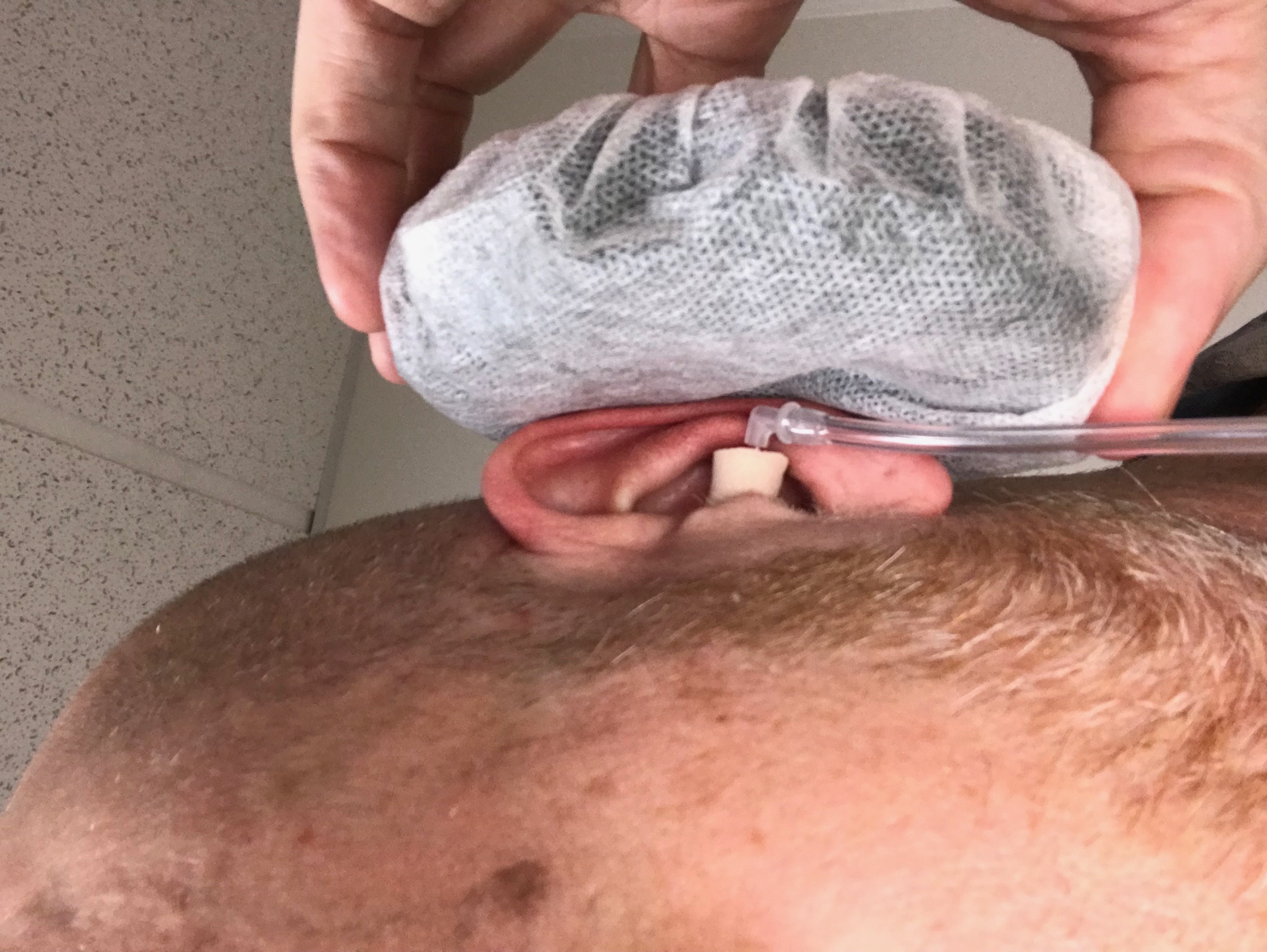 put the special ear plugs in his or her ear with the clear air tube attached and once the participant is in the coil, attach the air tubes to the white plastic boxes. To help quiet the system more and ensure that everything stays in place, use the black “earmuff” devices as well.
If you use this for audio delivery, you will not, of course, use the Siemens-supplied headphones or the Siemens-supplied microphone to talk to the participant. The MR Confon has both optical and analog inputs and has a simple interface for adjusting the sound level and balance.
The basic idea on this is that, since you’re not using the Siemens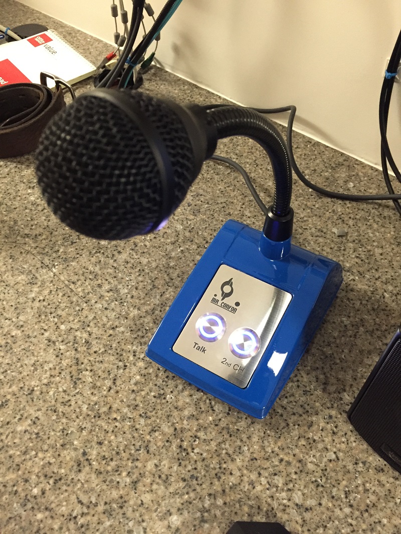 speakers or headset, talking to the participant must go through those headphones. To get that to happen, you use the other microphone on the desk. If you press the “Talk” button on the microphone, any other other audio delivery is muted and you’re talking to the person via the high-fidelity headphones. Adjust your volume (how loud you are to them) with the “volume” dial (middle one) while holding down the “Talk” button on the microphone. You’ll see the display shift to “Mike” (and yes, that’s wrong – it should be “Mic”).
With 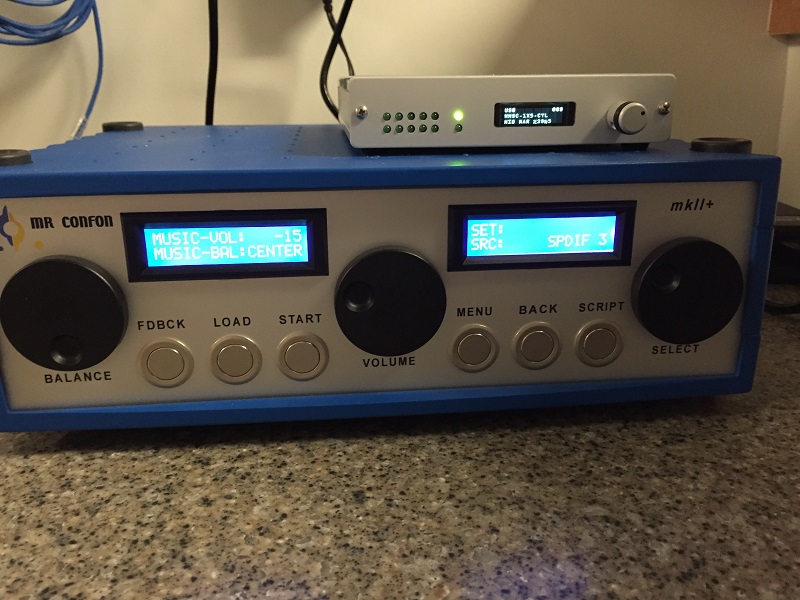 nothing pressed, adjusting the volume (or balance) knob adjusts the volume going out to the participant (-15 is a good starting point). You’ll also hear this on the speakers next to the monitor. You can adjust that volume separately by holding down the Volume knob (press it) for a second until it says “Music-MonVol” (monitor volume). Adjust as you like (-15 is a good start). The “FDBK” or “Feedback” parts refer to things we don’t have, so ignore those.
Sync pulse
The scanner outputs an optical signal to let you synchronize the data acquisition with your task. The optical signal can be sent either to a Siemens device, which converts this to a serial port signal (or TTL) or to the fORP 932 device used for recording participant responses. In the latter case, the sync pulse creates keyboard events with the number “5” (assuming you’re in the standard number-response mode).
Sync pulses are sent on each TR. So, if you’re used to this, great! If you’re used to only having the first real TR get the sync pulse, you need to set your experimental code up to reject the “5” responses coming in every second or two. In PsychoPy, just set the valid keys to be “1”,”2″,”3″,”4″ or something like that and it will ignore the 5’s, for example.
Eye tracker
The LiveTrack 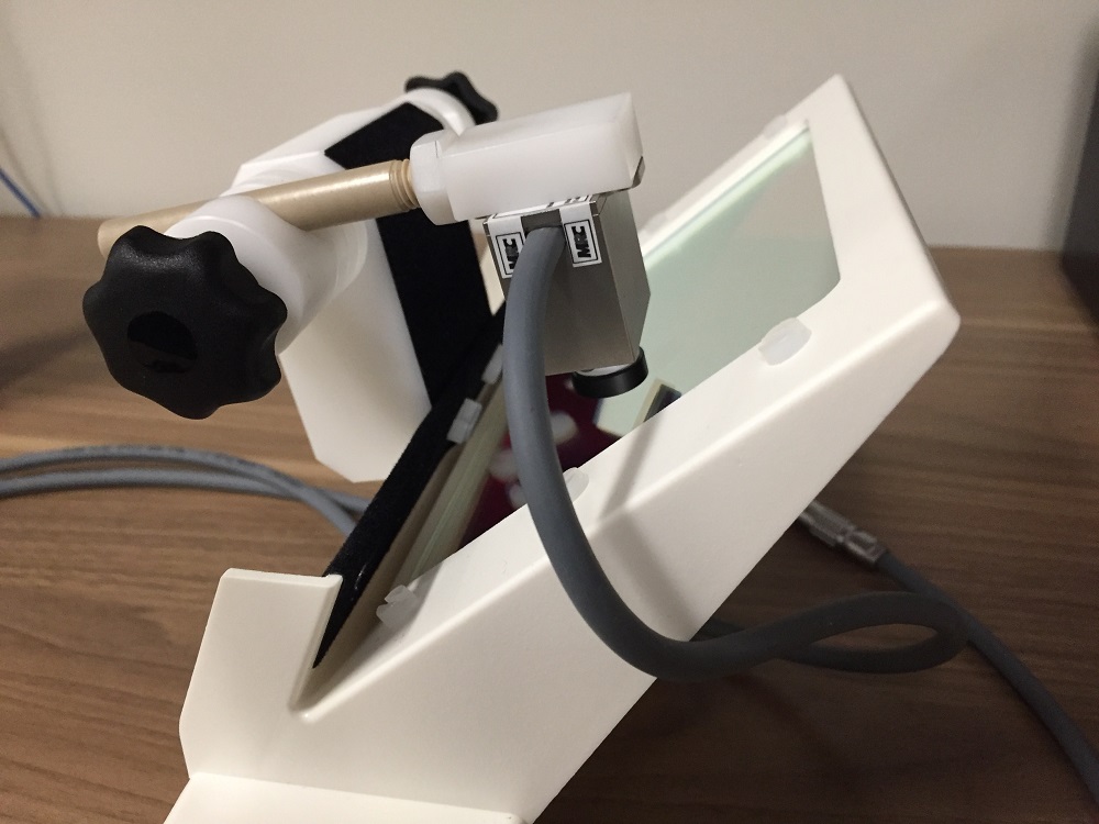 system uses a small camera mounted on a mirror assembly that you snap in place on the head coil (replacing the standard Siemens mirror). Participants look at the mirror (and at the BOLDScreen) and the camera looks through the mirror at the eye (it’s a cold mirror). The video from the camera is passed onto a pair of control boxes that do all the eye tracking and pupil diameter calculations. Plenty of details are found in the manual.
Cambridge Research provides a simple utility (find it on the computer Desktop) to calibrate the device for each person and to collect the data. It’s a solid way to make sure everything is working well and to align the camera to your participant’s eye and perform the calibration. Alignment is done by just loosening the black knob that holds the tan arm attached to the camera and adjusting the camera position until you get a good image of the eye. Having the BOLDScreen mirroring 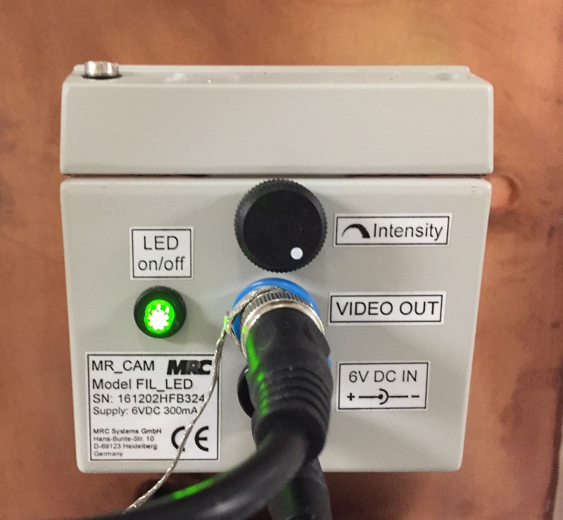 your computer display so that you can easily see this while with the participant helps a lot here! If you need to make the eye image brighter or darker, head back to the control room and adjust the LED “Intensity” knob on the LiveTrack control box mounted on the penetration panel.
While you can use the utility to capture your data, odds are you’re going to want a bit more. The LiveTrack is designed to work well with Psychtoolbox in either MATLAB or Octave (both on the computer). Type PsychSetupCamera to get going there.
MRI compatible glasses
For your participants who need vision correction and do not wear contacts, we have an MRI compatible glasses set. We go from -6 to +6 diopters in 0.5 diopter increments. Since each lens is nicely labeled via etching, it’s easy to keep them organized. Thus, there is no reason why they should ever be out of order, right?
Ideally, your participant either knows their “diopter” or brings a copy of the prescription for you to get close using the lenses we have. If you’re reading their prescription, OD=right eye and OS=left eye (their right and left, not yours while facing them). The only numbers you’ll look at are the “sph” or “spherical” correction (the first numbers). They might be something like -3 for a somewhat nearsighted individual (and it’s nearsightedness – inability to see clearly past reading distance – that we need to address for our scans as the monitor is ~4′ from the eyes). Don’t worry about “axis” or “cylinder” aspects as these are for astigmatisms and we can’t correct for them. But, we should still get close enough.
To check someone’s vision, we have a 6′ calibrated eye chart next to the scanner door. Standing with your back against the cabinet puts you at the right distance.
When changing lenses, it is important to make sure you don’t over-tighten the screw that holds the frames. Three half turns past the spot at which you could press the lenses into place is fine. Also, make sure to have the strap sitting low on the head so that the participant isn’t resting on it while in the scanner.
Mock scanner
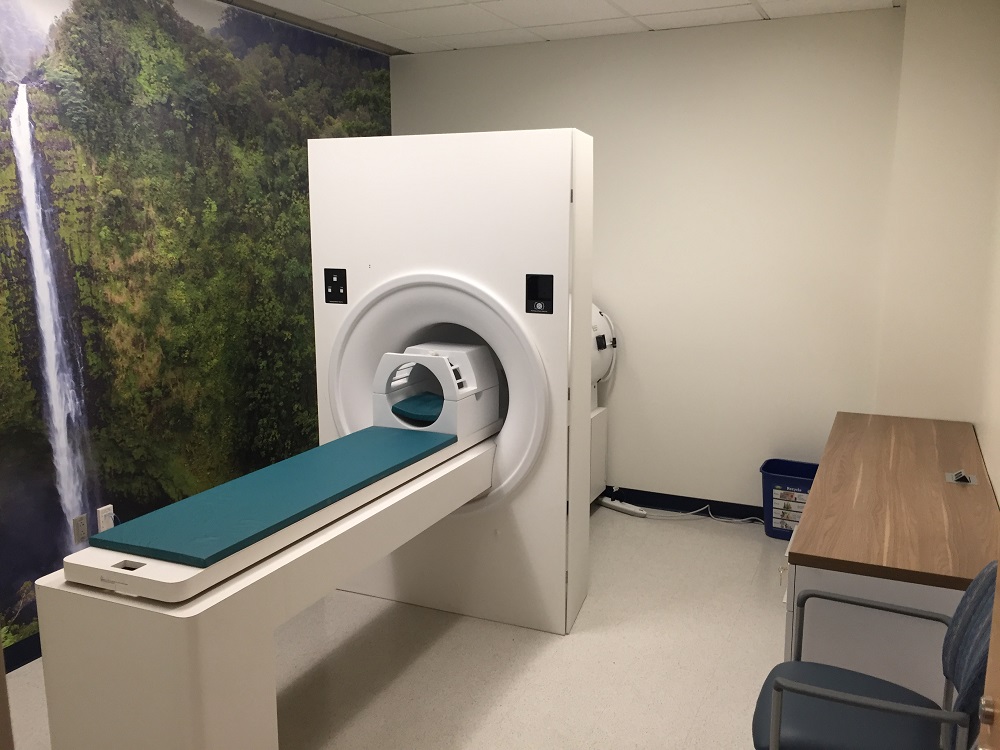 We have a Psychology Software Tools MRI Simulator for your use. It’s designed to provide a good approximation of what it is like to be inside an MRI environment. It features the lights, sounds, fans, and motorized table participants are exposed to during a scanning session and using this can help people learn to relax and stay still. Currently, we do not have a response box setup for the mock scanner, but you can pipe MRI sounds into it and teach participants what to expect during their scan.